Autocad Civil 3d Sample Drawings Of Ecosystem
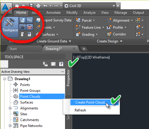
Now that we have addressed the 1000-lb gorilla that is CAD Standards, we can finally get started on creating the templates. The very first item you should address are Drawing Settings. Open your template and on the Settings tab of the Civil 3D Toolspace. Right-click the template name and click Edit Drawing Settings.
. Set drawings to scale and layers, plan and profiles using model space. Conducted conventional and Computer aided drafting (CAD) as applied to engineering architectural and civil drawing according to field notes created by surveyor.
Click the Abbreviations tab to set the abbreviations that will be using for label styles. Some common abbreviations that I find myself changing are RT for right, LT for left, BC for Tangent-Curve Intersect, EC for Curve-Tangent Intersect and GB for Grade Break. Of course, what you change will depend on the governing agencies standards in your area.
Click the AmbientSettings tab to set units, precision, and format values for common civil engineering measurement properties. Some of the settings that I find myself changing are the following:
- The precision value for distance and elevation (2).
- The precision for both angle and direction (6).
- The format for both angle and direction (DDMMSS).
If most of your work is in a specific area, you can set the appropriate coordinate system in the UnitsandZone tab (NAD83 CA, Zone III, US Foot in the lovely Bay Area). You can also set the default scale here.
Civil 3d
The ObjectLayers tab is where you will spending most of your time. Similar to how AutoCAD blocks have an insertion layer, Civil 3D objects have an insertion layer. This is where you define the insertion layer. You can also automatically add a prefix or suffix to the layer name (which I generally don’t do). To use the object name as the prefix or suffix, enter an asterisk (*) for value.
Working with the object layers can be tedious. First, you must make sure the AutoCAD layer exists. Then you must pick it in the Object Layers tab. There are between 50 and 60 object layers – hence the tedium.
I prefer to work in an Excel spreadsheet and copy the values from Excel to the template. The spreadsheet that I use is here. You can use the CMI Tools 2012 Import Object Layers command for this. To use the routine, first make sure that the Excel spreadsheet is open. Next, in Civil 3D, type, cmi_impol at the command line to run the command. Select Survey to load the survey layers or Civil to load the civil layers.
If you don’t like the fact that the layers also exist in AutoCAD, you can purge them. The object layer will then be created upon insertion of the object.
In the next part of this series, we’ll discuss Styles which many consider the “beef” of the template.

- [Shaun] Welcome to this AutoCAD ConstructionDrawings course.What we're going to be looking at during this courseis how we develop our drawings and our designsin AutoCAD to a point where we can actually issuea drawing for construction.Now the idea being is you develop your designsand you develop them in a waythat people can read them and obviously interpolatethe information from those particular drawingsand designs in order to construct something.
So you'll notice on the screen at the momentI have a drawing there and it's an elevation viewin a 2D AutoCAD drawing in the model space,and the drawing is called Industrial Building.dwg.Now you can see there that they're trying toobviously show you one side of a buildingthat needs to be built.You've got the grid lines there,you can see the glass, you can see the doors,you can see the windows.Now if I zoom out and roll back on the wheel,you'll notice that there's a lot of other designgoing on as well, all different elevationsof that particular building in the model space.
So what we need to do as we work through this courseis show people those elevationsand also annotate those elevationsso that people know the sizes of the objectthat they're going to build, whether that be a building,whether that be a gear wheel in a gear box for a car,or it might even be a road for example.So when we're developing our construction drawingsin AutoCAD, we'll obviously be showing youhow to basically present that information for construction.
That's the whole idea of AutoCAD is the abilityto design and then send that design outso that people can use that designand actually make something real,make anything as Autodesks say.So let's get into the constructions drawings courseand get you looking at the drawingsand obviously creating construction drawings from them,ready to send out to the stakeholders in any projectyou might be working in.